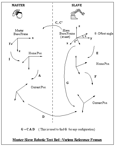


As a first step towards a general position control system , a cartesian control system has been set up on our test bed in which the slave's end effector mimics the translational motion as well as orientation of the master at any instant of time. The user puts on the helmet and finds a comfortable position. This position is sent to the slave as a reference and thereafter the two systems are activated and the slave's end effector translates and orients itself according to the motions of the user's head. The forward kinematics of the master are used to find the rotation matrix and translation vector that have to be enforced at the slave. The forces sensed at the slave are transformed into its fixed base frame and then communicated to the master where the joint motors are backdriven to apply forces on the user's head.
We have considered many reference positions and frames in our analysis. The master has a base frame whose axes are aligned as shown. It is made to calibrate itself and then move to a home position which corresponds to zero encoder readings on all the six joints. This reference frame has the same orientation as the base frame and we have assumed this to be the fixed base frame of the master. Hence they are connected by an identity matrix.

At any instant of time, the current position of the master is found by using its forward kinematics. For any set of joint angles, the position of the master has been found both by using D-H notation as well as geometrically. A schematic of the Perforce master robot shows the geometry as well as the D-H parameters used for finding the rotation matrix and translation vector.

The slave robot has a wrist mounted force sensor. The end effector sits in a nest when it is inactive. C is the matrix that describes the base of the slave w.r.t. the base of the master. The tool frame is oriented differently from the base frame and D is a rotation matrix which compensates for that. The nest position is taken as the reference frame of the zebra during implementation i.e. all translations and rotations for any new position have to be specified w.r.t. the nest position.
When the master is made to go to its home position, the slave is also commanded to go to a home position which has been taught to it. Then, the slave's wrist aligns itself with the master using the matrix G which is computed using the expression shown in the figure. At this position, the slave's coordinates are read and stored. As the master moves, its translation vector is added to the slave's stored coordinates to enforce a new position. The orientation of the master is mimicked by the slave's wrist by using G which is calculated on line.
The forces sensed at the slave are transformed into its fixed base frame and then communicated to the master. This data is then used to backdrive the motors in the x, y and z directions of the master.